
Adrift – Problem solving FS2 drift issues.
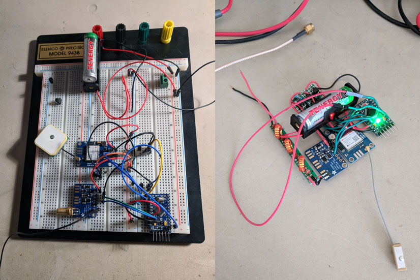
High altitude balloons are expected to drift, in the atmosphere. But Flying Squirrel #2 (FS2) has had some drifting problems of another kind. During construction as the FS2 flight electronics went from a breadboard prototype to final construction, a problem emerged. FS2 was not WSPRing clearly. In fact, it seemed to be more of a mumble than a whisper.
On the breadboard prototype the signals were being decoded almost every time FS2 transmitted a WSPR message. However, on the flight hardware, many of the WSPR transmit sequences were not decoding. Stranger yet, of the two types of WSPR messages FS2 sends (Type 2 & Type 3) one or the other would decode, but not both. Sometimes I would get the Type2 messages every time and an occasional Type3 message decode. Other times it was the reverse. Very strange!
WSPR is a protocol that decodes 100% or not at all. If you decode a WSPR message, you know you have perfect copy. What makes WSPR awesome is its ability to pull this perfect copy from incredibly weak signals and bad signal conditions. Often you can’t hear the signal with your ears, but the message will decode.
After constructing the first flight hardware, I ripped it apart and built a new version, making some improvements along the way. I suspected that maybe the proximity of the Si5351A board (Radio) and the Arduino Pro (Microprocessor) might be causing some interference. This change produced no improvement.
As I tested, I observed that the Si5351A drifted in frequency quite a bit as it warmed up from a cold start. A drift of about 25hz was clearly observable in the WSPR waterfall display. A WSPR signal has a total bandwidth of 6 Hz, so a 25Hz drift is significant. The main culprit of this drift is temperature change.

To conserve battery power, FS2 shuts off the radio board and the GPS when not needed. When FS2 is ready to send telemetry, it powers up the radio shortly before transmission begins. This causes some noticeable drift to occur as the chip begins to heat up a small amount. The FS1 balloon, got around this by transmitting a 5 second tuning signal that allowed the radio to warm up and stabilize from a cold start before data was sent. The WSPR protocol will not allow this extra warm up signal without causing interference to others, so that was not an option. With a little clever arrangement of the FS2 Telemetry schedule this problem was solved a large degree. A minute prior to sending the Type 2 WSPR message, FS2 will send a tuning signal followed by a FSQ telemetry message, on a separate frequency, at 3 baud which takes approximately 50 seconds to send. The radio board is left powered on, but not transmitting, so that the radio stays warm for the start of the 2 minute WSPR message type 2 transmission and then remains on until the 2 minute WSPR type 3 message is complete.
I had thought that this large drift was affecting the WSPR decodes, but after solving the drift problem, it was clear the problem of missing decoded message still remained.
To further diagnose the problem, I switched out the radio board with a new one from another manufacturer with a different design. I thought this new board would be more stable and might drift less. No change, that was not the problem.
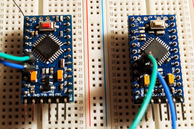
The GPS could not be causing interference because it is switched off long before the telemetry is transmitted. The only active component left to change is the Arduino. After a false negative result, which really confused things and wasted a lot of time, I did discover that changing Arduino boards made a difference. My Arduino on the breadboard was from a different batch than the newer ones I was using on the flight hardware build. They were of slightly different construction and could be easily identified by the color of the reset button on the board. My “White button” Arduino worked almost flawlessly on the breadboard and the newer “Red button” models failed most of the time.
My thoughts turned to some kind of interference that might be emanating from the Arduino and affecting the signal quality somehow. I tried adding filtering/bypass capacitors to the pins on the boards and power rails. This is a very common solution to noise/interference problems. This again had no effect. Odd!!!
Two weeks into this problem, I could clearly demonstrate that swapping a white button Arduino with a red button Arduino caused failure. I ordered a few more white button models and tested with them and had mixed results, none of which were great. They were better or worse but not perfect. What was the difference between these boards?
As I worked to diagnose this problem, I investigated the WSPR source code and learned more about the protocol to help me debug this problem. I learned, the WSJT-X program, which is the most modern version of WSPR software, logs some useful information not seen on screen. The file ALL_WSPR.txt contains a record for each decode it achieves. Much of the logged information is the same as shown on screen, but there are a few extra fields of information. The most useful field, for solving this problem, is a count of how many times the decoder passed over the signal data before successfully decoding a message. The program will attempt up to 10,000 passes to decode the all the messages it can find in the 200 Hz audio passband. Strong clear signals only need one or two passes to decode. Weaker and more noisy signals, require many more passes. Any message not decoded after 10,000 passes is lost. (Not quite true, but that is another story). In effect the number of passes logged is a quality indicator of the signal. Low numbers mean the signal was of sufficient quality to only require a few passes to decode, i.e. it is a really good clean signal.
//
//  The 2nd to last number is the # of passes required to decode.
//  The type 3 messages, with the grid locator DM13IU should be every other decode,
//  but many are missing.
//
180327 1342 2 17 -0.57 14.0970279 KJ6FO/B 13 -3 9 0
180327 1344 2 18 -0.57 14.0970255 <KJ6FO/B>; DM13IU 13 -1 4545 48
180327 1348 2 18 -0.27 14.0970250 KJ6FO/B 13 -1 2002 -8
180327 1350 2 19 -0.23 14.0970243 <KJ6FO/B>; DM13IU 13 0 7414 0
180327 1400 2 18 -0.53 14.0970246 KJ6FO/B 13 0 5 0
180327 1406 2 19 -0.66 14.0970245 KJ6FO/B 13 0 10 0
180327 1412 2 19 -0.74 14.0970245 KJ6FO/B 13 0 5373 16
180327 1414 2 19 -0.40 14.0970238 <KJ6FO/B> DM13IU 13 0 1888 0
180327 1418 2 18 -0.32 14.0970243 KJ6FO/B 13 -1 2453 -8
180327 1420 2 19 -0.45 14.0970236 <KJ6FO/B> DM13IU 13 0 6675 32
180327 1424 2 18 -0.40 14.0970236 KJ6FO/B 13 -1 4 0
180327 1430 2 19 -0.66 14.0970231 KJ6FO/B 13 0 8 0
180327 1436 2 19 -0.74 14.0970230 KJ6FO/B 13 0 4969 0
180327 1438 2 19 -0.40 14.0970224 <KJ6FO/B> DM13IU 13 0 5363 16
180327 1442 2 18 -0.70 14.0970224 KJ6FO/B 13 0 1055 0
180327 1448 2 19 -0.40 14.0970222 KJ6FO/B 13 0 12 0
180327 1454 2 18 -0.74 14.0970226 KJ6FO/B 13 0 18 0
180327 1500 2 18 -0.40 14.0970230 KJ6FO/B 13 0 20 0
180329 1538 3 16 1.26 14.0971692 KJ6FO/B 13 -4 1 0
180329 1540 3 17 1.69 14.0971666 <KJ6FO/B> DM13IU 13 -1 1 0
180329 1544 4 15 1.30 14.0971675 KJ6FO/B 13 -4 1 0
180329 1546 2 16 1.82 14.0971661 <KJ6FO/B> DM13IU 13 -1 1 0
180329 1550 2 17 1.35 14.0970165 KJ6FO/B 13 0 1 0
180329 1552 3 17 1.69 14.0970173 <KJ6FO/B> DM13IU 13 -2 1 0
180329 1556 3 17 1.47 14.0970172 KJ6FO/B 13 0 1 0
Looking at the logs as I was working to debug FS2 WSPR, I noticed that even on my best Arduino white button board the passes count was often not low. So even my best board was far from perfect. Something deeper was going on.
My thoughts then turned to possible variations in the Arduinos internal clock that might affect timing. A WSPR transmission sends 162 tones at 1.4648 Baud. Converting Baud to seconds (The inverse of Baud = 1/Baud) gives us that each tone is should be transmitted for a period of 0.682667 seconds. The library code I derived from (https://github.com/etherkit/JTEncode) had an Arduino delay function of 683 milliseconds (0.683 sec plus or minus a few milliseconds of error) before changing to the next tone frequency. I suspected that the roundoff between these two values might accumulate and cause the problems, along with some variance in the Arduino’s clock timing.
I was able to measure the length of these tones by setting a GPIO pin on the Arduino high and low for each tone change and measured the time interval on my oscilloscope. I found there was a clear deviation from the desired time of 0.682667 seconds. Ah HAH!…. almost. The time difference was on the order of 5 milliseconds too long on each tone, far more than the small round off error I was expecting between 0.683000 & 0.682667 seconds. (aprox 1/3 of a millisecond rounding error) Adjusting the timing code to subtract the 5 milliseconds from each tone resulted in much better decoding. I clearly saw that the decodes got way better in the ALL_WSPR.txt file. This was clearly the problem, but the numbers made no sense yet. This was a large deviation from the WSPR specifications.
Upon further investigation, I discovered the function set_freq() call that sets the frequency on the SI5351A is a slow call.
It takes about 5 milliseconds to change frequency, and also has some variation between individual calls. The original code did not
account for this significant delay.
// Loop through the WSPR symbols and set tones

for(i = 0; i <; symbol_count; i++)

{

si5351.set_freq((freq * 100) + (tx_buffer[i] * tone_spacing), SI5351_CLK0);
delay(tone_delay); // Wait for the next tone to be sent. tone_delay has the value of 683 for WSPR

}
I changed the code to this:
// Loop through the WSPR symbols and set tones
for (int i = 0; i <; symbol_count; i++)
{
unsigned long starttime = micros(); // Get Start time
 si5351.set_freq((freq * 100) + (tx_buffer[i] * tone_spacing), SI5351_CLK0);

while ((micros() - starttime) < tone_delay) {}; // Wait until time is up. tone_delay is 682667UL

}
This new code makes timing much more accurate. First it uses a Micro-second timer micros() which has the resolution to give a much more proper 0.682667 delay. (Plus or minus a few microseconds error, that averages out). There is no accumulating roundoff of the delay time now. The code also considers the time needed for the frequency change function by starting the time just before the function call set_freq(). The latter error was the most significant source of the decoding problems.
Problem solved!!! But there remains a mystery of why did different Arduino boards have different rates of decode success? This fact disquised a software problem as a hardware problem which lead to two weeks (not full time) of hair ripping diagnostic delay getting working flight hardware. I suspect that there is just a slight difference in timing between the boards and the timing error was just at a threshold of good enough for a decode on the white button board. The red button version might just a bit slower pushing past the threshold and failing. This would probably be a very small amount of difference, but maybe enough to push past a threshold of acceptable signal quality.
This experience leaves me with a few observations:
Don’t fully trust that code from others (i.e an Arduino Library) works 100%. When something is not right, check into it. Of course, your own code can have flaws too.
Use the process of elimination. Swap parts until you get a better or worse result and then assess why you got a new result. Be orderly and replace one thing at a time. Changing more than one variable can lead to confusing results and a confused builder.
“Success teaches us less than Failure does”. Had this just worked, by luck, the first time I built the flight hardware, I would have moved on to the next issue in ignorant bliss of a problem. But the failure caused me to learn a lot about the real underling problems in the code (There were a few actually) and led me to a deeper study of how WSPR is decoded. Failure is a good teacher.
Perseverance pays off. I was very frustrated at times diagnosing this problem. My frustration was enhanced by a few conflicting false positive and false negative test results. The problem seemed to change forms at times. I walked away dead tired some nights after hours of test. But I was not going to give up!
Retest over and over again. Retesting led me to find the variations in boards, which again was an unsatisfying result. I wanted all boards to work or know why some did not work while others did work. I dug even deeper and found the timing error, but not one that made sense to me at first. The magnitude of the time error, approximately 5 milliseconds, was too far off to be explained by hardware alone. So, I went back to the software, which I had not suspected until late in the cycle.
In the end I am happy that I have a working WSPR transmitter on FS2. All the frustration quickly dissolves when you achieve a successful result!!!
There are two remaining issues to solve and then final FS2 construction to be completed.
The issues:
- A frequency drift due to the very cold temperatures at high altitude. This is not a big problem for FSQ, but WSPR will have problems. From a warm day at ground level, to frigid cold several miles high, the radio will drift beyond the very narrow 200Hz bandpass window of the WSPR network decoders on the ground. FS2 has a thermometer onboard so I am developing a software solution to adjust frequency with measured temperature changes. I think this will work well to solve the problem.
- To prevent FS2 from freezing up like the FS1 mission, an insulated container for the electronics must be designed. This container must be light weight and keep the innards from freezing by retaining onboard heat. This may be a challenging problem but should be solvable.
The final drift issue for FS2 is a schedule drift. FS2 won’t be ready for an April Launch as initially planned. May is looking much more likely. Stay tuned!
73s de KJ6FO
2 comments to “Adrift – Problem solving FS2 drift issues.”
Dan WA6PZB - October 3, 2018
Hi Don,
I just wanted to drop you a quick line and thank you for this post regarding the JTEncode timing issue you found. I ran into to this exact issue after adding addition libraries to my code and I began having issues decoding the messages. After I added the timing fix the issue seemed be resolved. I will do more testing this week.
I know keeping a detailed blog can seem like a lot of effort but if it helps one person it is worth it in my mind, so I wanted to let you know and give you my thanks!
If your going to do any more balloon launches and need any assistance let me know, we are not that far from each other.
73
Dan
admin - October 8, 2018
Hi Dan,
Thanks for the comment.
I am thrilled that my fix was helpful to you! Anytime I am banging my head against a problem like this (for days!), I wonder if others have had the same issues and I hope to assist them so they can avoid the problems I found.
I would enjoy hearing what project(s) you have under way with the Jt8 Library and If I can offer advice/assistance, don’t hesitate to ask.
I want to launch Flying Squirrel #3 soon. I had hoped for October launch, but now November is probably more likely. I will announce it here and on Facebook soon. I welcome people to join us at launch or monitoring the telemetry from home. FS3 will be be very similar to he FS2 flight.
My apologies for a slow response to your posts. Apparently the blog is not sending notices to my email. I will get that fixed.
73s!
De KJ6FO Don