
Build a portable Allstar Link Hotspot – Part 2 Radio mods
Modifying the Baofeng BF-888S radio
Start with Programming the Radio
Before you modify the radio, it will be easiest to program your BF-888s first
As shipped the BF888s is pre-programmed with commercial frequencies. To set up the radio on the ham bands it needs to be programmed. Info on how to program the radio is available here. There also guides published on YouTube. I recommend that you get an official FTDI Programming Cable as they will cause less grief that the knock off cables available for a few dollars less. Knock off cables do not have the official FTDI chip inside and the Windows driver (by default) wont work with the knock off versions. This one is available on Amazon.
The BF888s can be programmed to operate within the Amateur Radio 70cm band. I operate my node as a simplex repeater. 70cm band plans vary a lot across the US, so you should investigate the best simplex frequencies for your area. In my area (S. California) 445.000 Mhz is designated as a remote base frequency, so that is the frequency I use. Since the BF-888s can be programmed with 16 channels, I have programmed a few different simplex frequencies that I can use during my travels.
Be sure to follow your local countries rules and do not operate a Ham radio Allstar node on frequencies that you are not authorized to use for this purpose. (i.e. obey your local laws)
This article describes the basics of the radio mods needed: https://hamvoip.org/hamradio/baofeng888/
The Baofeng BF888S radio undergos frequent changes to the printed circuit board design over time. The radios I ordered in the summer of 2018 were different than the radios shown in the article linked above and other articles I could find. While the PCBs are different all of the needed signals are still available on the pcb, but the locations of the connection to the circuit board have changed.
To get to the radio PCB, the radio first needs to be disassembled:
- Remove the battery pack from the radio.
- Pull the power/volume knob off. Pull hard and straight off the shaft and it will come off.
- Pull the channel selector off in the same way as the volume knob. This knob, on my radios, required more force to remove. A pair of pliers may help getting a better grip on the knob. Just pull straight to avoid stressing the switch on the PCB.
- Unscrew the Antenna
- Remove the two Torx screws at the bottom of the battery compartment. These are T-8 screws
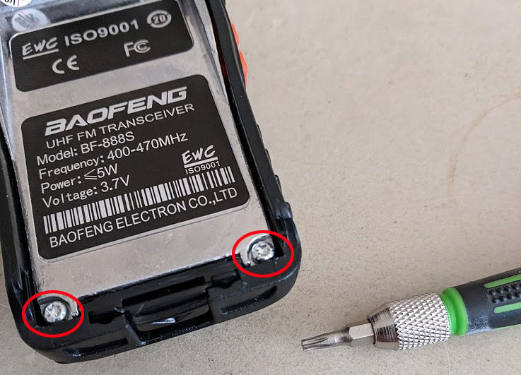
Location of Torx screws - Remove the two Phillips head screws from the upper back side.
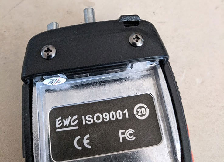
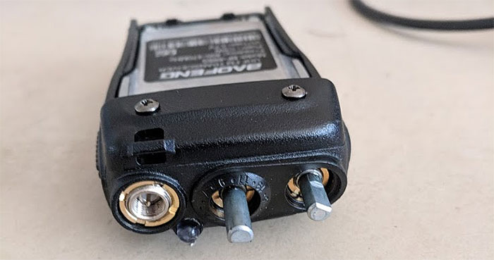
Phillip[s screws location - Remove the retaining nuts around the Antenna and two knobs at the top of the radio. The nuts are usually not on too tight and can be removed with a small flat blade screwdriver by pushing the blade into the slots and pushing the nut around counter clockwise.

- Lift the bottom, where the Torx screws were of the metal body up a little bit.
- Pull downward on the metal body until the knobs and antenna connector are free from the case.
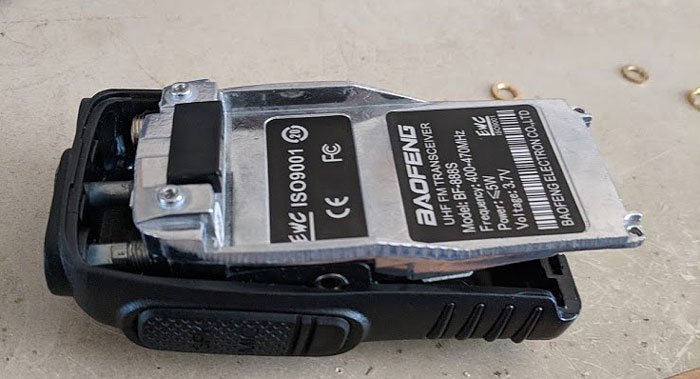
- You can now open the case and body like the two sides of a book to expose the PCB.

- Unsolder the two black speaker wires to disconnect the body from the plastic case. My design does not use the case so throw the case into the used parts bin (or trash)
There are six wires that need to be soldered to the board.
- Power
- Ground
- Carrier sense (COS)
- Push to talk (PTT)
- TX audio
- RX Audio
Unfortunately, on my version of the radio, the COS on the bottom side of the PCB and requires additional disassembly. Some previous version of the radio radios have a point on the front side to make this connection, but on my version, I was not able to find it.
Remove the PCB from the metal body.
- Remove the three screws (Green Circles) attaching the PCB to the metal body.
- Unsolder the antenna and power connectors from the board. (Red Circles)
- Lift the PCB off the metal body

Attach the COS wire.
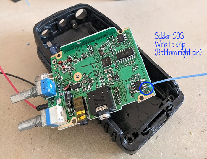
The COS senses if there is a carrier on the receiving frequency. COS goes high when the squelch open (i.e. a signal is received) Carefully attach a fine wire to the pin on the integrated circuit shown in the picture. It helps to tin the stripped end of the wire first and then touch it to the IC pin and quickly heat with the tip of the soldering iron. Use caution to not overheat the IC pin and damage the IC.
Add a little dab of silicon glue to secure the wire to the PCB. Avoid using RTV type silicon because it produces an acid during the curing process and this may damage the PCB. A dab of hot melt glue will also work. This will relieve any strain on the delicate connection when the wire is pulled on.
When the glue is cured, reattach the PCB to the metal body with the screws and solder the power line and antenna connector back onto the PCB.
The rest of the connections:
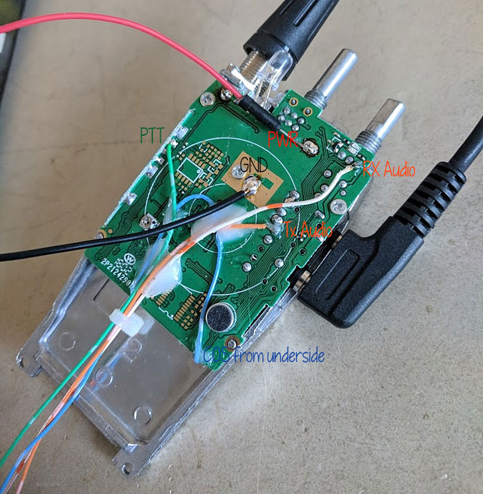
Attach wires as indicated in the picture for Power, Ground, PTT, TX audio and RX audio. The radio can draw around 1 amp on transmit, so use a heavier gauge hook up wire (20-22 awg) for power and ground.
When done soldering, gather the wires and secure them with a dab of silicone or hot melt glue to give some strain relief to the connections and let dry.
Tip:
Leave the wires long for now. You can cut them to size when you attach them to the interface board (described later)
8 comments to “Build a portable Allstar Link Hotspot – Part 2 Radio mods”
Mike - KA9CQL - November 22, 2018
I think you misquoted the So. Cal Remote Base frequency – It says “455.000 Mhz is designated as a remote base frequency,” I believe you mean to say “445.000 Mhz is designated as a remote base frequency,”
admin - November 22, 2018
Mike, You are correct. I fixed the typo. Thanks for catching this. 73s
Tom - January 12, 2019
ic chip can not take alot of heat and is to small for me to get solder on or solder is not good
admin - January 16, 2019
The trick is to tin your wire, and position the wire against the pin and just touch it quickly with the soldering iron. Just”Tack it” down. If you can lower your temperature on the iron that adds an extra margin of safety. It will be a weak joint, so reinforce it with some NON-RTV silicone adhesive.
admin - January 16, 2019
This video may help you with some additional tips. For example using flux. See how he initially tack the pins. That is more or less what you are going for.
https://www.youtube.com/watch?v=7B_-qmJLfng
Dan - July 6, 2019
Is the COS active when PL is detected or just RF or the RX freq?
I am looking for the PL COS in particular. Thanks! Nice pictures with details.
admin - July 6, 2019
Good question. I think it is based on the PL. I will be doing some work on my node tomorrow and I can verify while it is open.
admin - July 8, 2019
I confirmed that the COS will not activate unless the CTSS is correct (Assuming the BF888 is set up to listen for the CTSS code)