
Build a portable Allstar Link Hotspot – Part 4 The Glue between sound fob, radio and power
Now that you have both the Radio and Sound Card FOB wired up and your Raspberry Pi on hand we need to tie everything together.
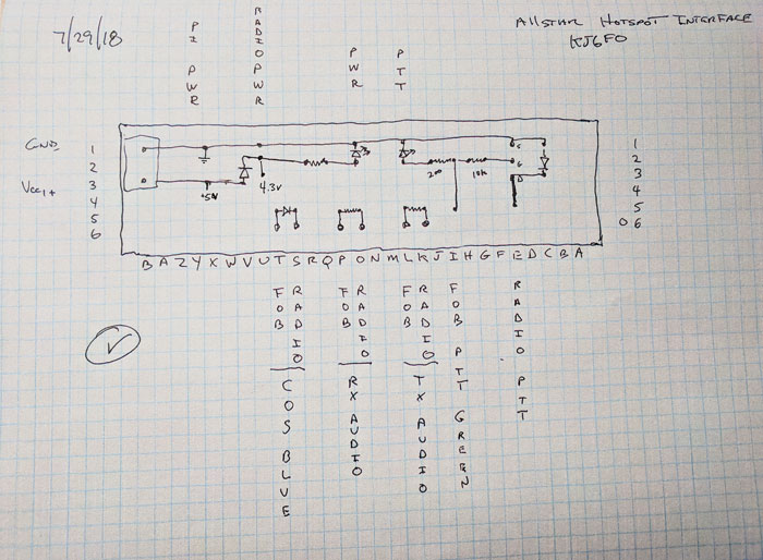
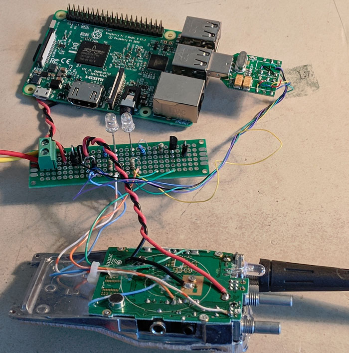
Most of the articles I found put the required Fob to Radio interface electronic components in-line with the wires to the radio or the sound fob. Since my build is going to be boxed into a single enclosure, it will have plenty of room inside, so I elected to build a separate board that would connect the radio and fob together as well as handle the power connections. This board is the “glue” the connects the separate parts of the system. The wires from the radio and sound fob are attached together via this board. This board also has LEDs to indicate power and PTT status. It also has a power connector for 5v input and produces a lower voltage required by the BF888s radio.
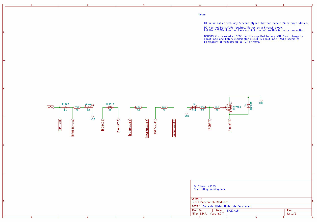
Full size Allstar Interface Board Schematic Diagram (PDF)
To power the Raspberry Pi a 5v supply is needed, but the radio operates at a lower voltage so a voltage drop is needed. The 5v power source is connected to the Raspberry Pi to power it up.
A diode (D1 RL207) is used to drop the voltage for the radio. The BF888s is rated at a 3.7 volt input, but I found that a fully charged battery is 4.2 volts and a battery eliminator made for the BF888s actually outputs 5 volts. It seems that the radio’s input voltage is flexible. D1 drops the voltage from the 5v supply and powers the radio. I tired two diodes to make a larger drop and the radio started acting up, so I went back to the single diode. Most any silicon diode will work as long as it has about a 0.7v drop. Since the radio can draw about 1 amp, the diode should be rated at 2 amps or above. The diode does get warm on a long transmit, but not alarmingly hot. Finally, the power is sent through a green LED to indicate that power is on.
The PTT circuit uses a 2N700 FET transistor used as a switch. When the FOB PTT line goes high it turns Q1 on which will connect the radio PTT line to ground, keying the radio. The FOB PTT line will also light a Red LED to indicate that the radio should be transmitting. Diode D5 protects the transistor from inductively induced current (Flyback) that may come from the radio. For the BF888s radio , since it does not seem to have coils inline with the PTT, this is probably overkill.
The COS line from the radio passes though a reverse biased diode D3 to the fobs COS line. The diode protects the sound FOB from any large current that may be on the line from the radio.
Resistors R2 & R3 are used to set the RX and TX audio to appropriate levels for the FOB & Radio. You can fine tune the levels withing the Allstar software if needed.
To finish off the circuit, I added an Anderson power pole connector to the input side of a 12v to 5v buck converter and this allows me to connect the rig to any convenient 12v power source in my shack (All my shack power uses Anderson Power poles) I also constructed a cigarette lighter plug to a power pole connector so I can run the node from the dash board plug.
It is time for Pi!
Lastly the Raspberry Pi is connected to the 5v power from the interface board. While the Pi has header pins labeled 5v and Ground, it is not advisable to connect power directly to these pins. They were designed for output voltages. Connecting power to these pins leaves the Pi unprotected from voltage spikes that are likely to occur in a near RF environment.
The Pi is normally powered from a micro USB connector which supplies the required 5v. This input is protected from nasty voltage surprises, so it is the preferred way to connect power. However, I do not want to bother with a USB connector, so I directly soldered the power wires to the underside of the Pi. +5V connects to the PP1 pad on the RPi and Ground connects to PP3.
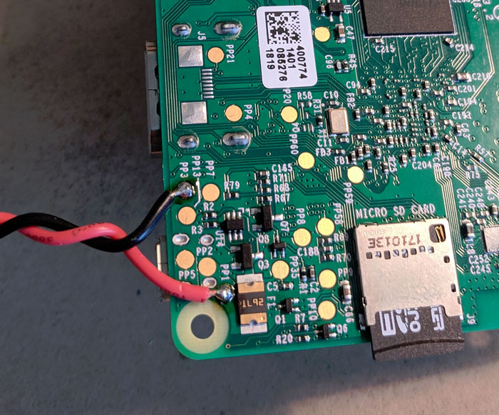
Use caution when soldering the 5V line as the PP1 point I soldered to is surrounded by ground plane and could easily result in a short. After soldering check the resistance between your power and ground and make sure it is not at or near zero ohms (i.e. short).
Finishing up
Once the hardware is setup, installing and configuring the Allstar software is next. This process is described in this article. Before you download the software and install it, go onto Allstartlink.org and create an account and request a server and node (as described in the linked article). It may take a few hours to days before a volunteer configures your node and assigns a node number to you. So get this process underway soon as you can. Run though the set-up procedures as described in the set up article.
I was leaving on a trip shortly after building my Allstar Hotspot, so I just threw the node into a Tupperware type box and plugged into my 12V dashboard power port (i.e. Cigarette lighter socket). This worked very well, but it is not as robust as I desire for continuing travels. So the next step is to build an enclosure to make the Allstar Node truly portable.
73s Don KJ6FO
4 comments to “Build a portable Allstar Link Hotspot – Part 4 The Glue between sound fob, radio and power”
Brian - January 8, 2020
Hello,
First thanks for putting this Allstar Build together it is very detailed and has got me most of the way, except of one issue. The problem I am having is concerning PTT triggering, it is not operational. However Allstar reporting is saying it is “PTT-Keyed” via Supermon so I know the command is being sent.
I checked the sound fob (Pin 13) to see if it was sending voltage to Pin 2 of the 2N7000 and it is not. I think one of two things is happening.
1) The Sound FOB is defective and failing to send voltage to Pin 2 of 2N7000
2) I am missing a configuration setting within the IMG
I am leaning toward #2 as the issue but want to get your thoughts first. Also I connected this new node to a existing node and everything seems to be working as it should just missing the TX audio because it will not key the PTT.
admin - January 9, 2020
Brian,
Thanks for the compliments.
Here are my settings:
From the Main menu select #12 for the simpleusb menu Select option P to display all of your settings. They should match mine.
Active simpleusb device stanza: [usb] ————————————
S) Select active USB device stanza
V) View COS, CTCSS and PTT Telemetry using real-time display
P) Print Current Parameter Values
2) Set Rx Voice Level (using display)
3) Set Transmit A Level
4) Set Transmit B Level
B) Toggle RX Boost Mode (currently Disabled)
C) Toggle Echo Mode (currently Disabled)
D) Flash (Toggle PTT and Tone output several times)
E) Toggle Transmit Test Tone/Keying (currently Disabled)
K) Manually key COS (currently Unkeyed)
F) Toggle PRE-emphasis Mode (currently Disabled)
G) Toggle DE-emphasis Mode (currently Enabled)
H) Toggle PLfilter Mode (currently Enabled)
Q) Toggle DCSfilter Mode (currently Disabled)
I) Toggle PTT Mode (currently active LOW)
J) Change COSFROM Mode (currently “usb”)
L) Change CTCSSFROM Mode (currently “no”)
M) Change RXONDELAY value (currently “0”)
N) Change RXAUDIODELAY value (currently “0”)
W) Write (Save) Current Parameter Values
0) Exit Menu
Please enter your selection now: p
Active simpleusb stanza: [usb]
USB device String: 1-1.5:1.0
Card is: 0
Name is: usb
Rx Level: 500
Rx no-delay: 0
Rx audio-delay: 0
Tx A Level: 500
Tx B Level: 500
preemphasis: no
deemphasis: yes
plfilter: yes
dcsfilter: no
rxboost: no
PTT: Active LOW
PTT status: Un-Keyed
CTCSS (input): Ignored
COS (input): CM108/CM119 Active HIGH
COS (test): Un-Keyed
COS (composite): Un-Keyed
—————————————
Check the PTT, it should be active LOW. If this setting is not Active LOW that would cause you problems.
Also try Option V) View COS, CTCSS and PTT Telemetry using real-time display
When you are just listening you should see:
REALTIME RX TELEMETRY DISPLAY:
COS | COS | COS | CTCSS | CTCSS | PTT
(composite) | (input) | (test) | (input) | (override) |
CLEAR | CLEAR | CLEAR | IGNORE | CLEAR | CLEAR
When you are transmitting from another radio (Ex a Handheld) you should see the COS columns in a KEYED state:
Transmitting with radio to the node (Ex. a handheld)
REALTIME RX TELEMETRY DISPLAY:
COS | COS | COS | CTCSS | CTCSS | PTT
(composite) | (input) | (test) | (input) | (override) |
KEYED | KEYED | CLEAR | IGNORE | CLEAR | CLEAR
And right after you unkey your handheld the PTT should show keyed and the node should be transmitting with a beep tone:
REALTIME RX TELEMETRY DISPLAY:
COS | COS | COS | CTCSS | CTCSS | PTT
(composite) | (input) | (test) | (input) | (override) |
CLEAR | KEYED | CLEAR | IGNORE | CLEAR | KEYED
admin - January 9, 2020
Some additional tips for diagnosing PTT problems:
If there is no voltage going out to the center pin of the 2n700, yes it will not key the radio. And I agree that your options #1 and #2 could be the cause. A possible cause #3 could be that your solder joint to the PTT pin on the sound FOB chip could be misplaced or faulty. (Ex. Wrong pin, Cold solder joint or a solder blob shorting it out.)
A couple of tests to try just to eliminate other causes:
1. Connect a source of 3.3V (Between D1 & R1 will work) to the point between R4 & R5 to “Hot wire” the PTT and see if it does in fact trigger the radio to transmit? If you do this the LED (D4) should light up and the radio should key. This will verify the 2n700 and PTT line are connected and working correctly.
2. If #1 test above fails, try shorting the Radio PTT line to ground. This should key the radio. If not then the PTT wire is not correct on the radio. If the test above fails and this one works then maybe the 2n700 went bad?
Assuming your get the radio key up with one of the two tests above, then its time to investigate the sound fob or the settings as you suggested. I am in the process of booting up my portable node (I have not used it for a few months) and I will send over a list of my settings to you shortly. You should get your settings to match. If you do match and it still fails then maybe its the sound fob at fault. I have not seen this happen, but I assume it could happen.
73s de Don KJ6FO
Brian - January 10, 2020
Thanks Don,
In my case it was a defective sound card, acquired a new one and install now I am on the air. I think one of two things happened that damaged the sound card.
1) It was defective from the factory. If I did another one I would confirm operation before making modifications.
2) While attaching the PTT wire to GPIO Pin 13 of the CM119 I applied too much heat and damaged it. This is possible as it took me a few tries to get it attached. Good news is these Sound Card are cheap I would advise to buy a few and if you are a Amazon Prime member you can return the unused ones for free.
Thanks for the support
73
Brian KI5GKF
P.S. The node associated with this build is 50908 and can been seen on my QRZ page