
Flying Squirrels #5 – The Flight controller
 The flight controller of Flying Squirrel #1 is the brains of the flight. The controller will measure the environment around the balloon, format the data into a Telemetry message and transmit the telemetry signal back to the ground using the chosen protocol (FSQ) for the flight. The flight controller will also manage the power to the radio and weather sensor boards, turning them off when not needed to conserve power and prolong the mission.
The main hardware components for the flight controller consist of:
- Arduino Nano Pro-Mini 3.3Volt Microprocessor.
- Adafruit Si5351A Clock generator (Radio)
- Adafruit BMP085 Pressure and Temperature sensor. (Weather sensor)
- Low Pass filter to filter out unwanted harmonics
- 2N7000 MOSFET Transistor – The power switch to peripheral boards
- A 3.3v 400Mah battery for power.
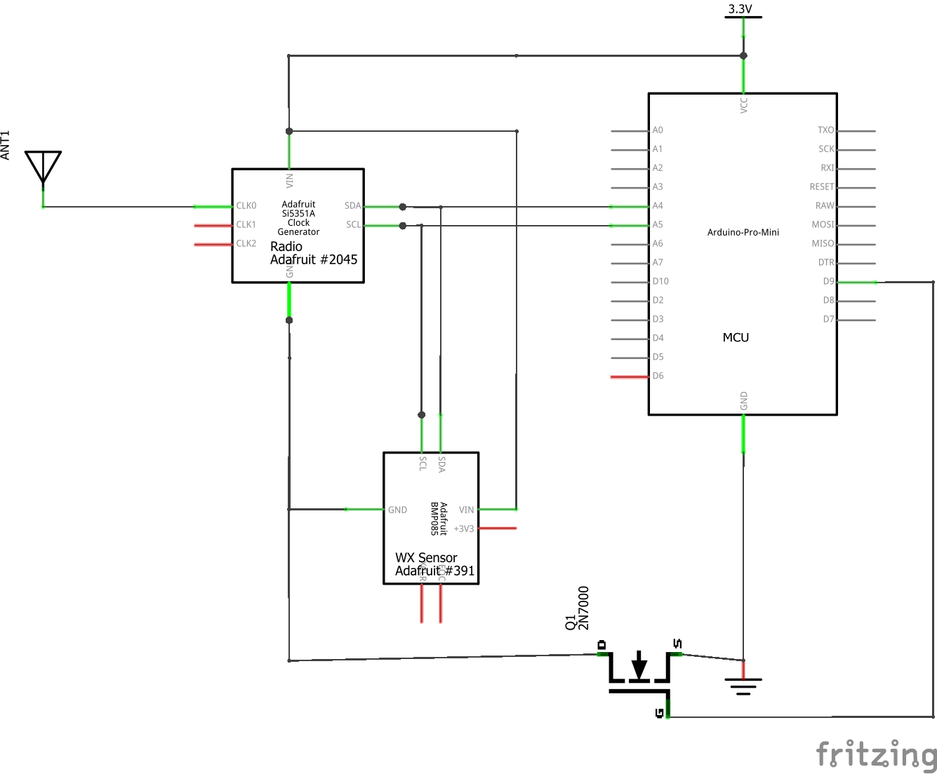
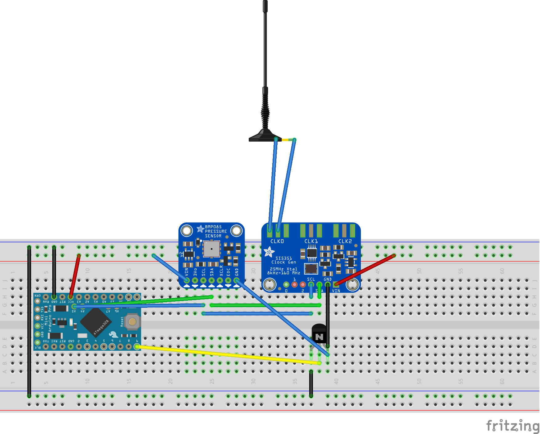
I drew up the following schematic diagram using Frizding. I am new to this program so the drawing may not be perfect, but the connections are accurate (if not perfectly straight)
The balloon will be powered by a 3.3 volt LifePO4 battery. I chose 3.3 volts because I can power the electronics with a single battery. The alternative of 5 volts would require more batteries or a boost converter to get the 5-volt source of power. Either of these two solutions would require more weight/complexity than a single battery cell. In my HAB project every bit of weight matters, so “less is more”. For my prototyping of the circuit I use either the USB power from my development computer or a lab power supply that I can use to get rough power consumption measurements. In actual flight, the batter will power the show.
The Arduino Pro-Mini is light weight and has enough ability to run the Telemetry for this flight. There are only 5 connections to the Pro-Mino board.
VCC – Power 3.3v
Ground
A4 & A5 I2C data bus interface to the Radio and WX board
Pin D9 – Control of power via the 2N7000 MOSFET
The SI5351A and BMP085 are also connected to 3.3v power and to the I2C data bus. The only “unusual” connections for these boards is the ground. Instead of going to direct to ground these boards are connected to the Drain of the MOSFET. Then the Source pin of the MOSFET is wired to ground.
Pin D9 of the Pro-Mini is connected to the Gate pin of the MOSFET. When PIN D9 is low, the radio and weather boards are cut off from ground and thus are “Powered Off”. When D9 is high, then the MOSFET will connect the boards to ground, allowing current to flow through the boards and “Power Up” the boards. MOSFET Switch Circuit
The Si5351A board has three outputs called CLK0, CLK1, CLK2. We only need one output for this project so the lowpass filter and antenna are connected to CLK0.
The low pass filter is not shown in this schematic. I consider this filter as part of the antenna system and thus I only show the antenna in the diagram. Details about the filter and antenna are in the prior article.
Power consumption
The Nano Pro-Mini consumes about 5 Milliamps. It is possible to put the pro-mini to sleep at times to save power, but this requires more complexity and this flight will last many hours as it is without the trouble of sleeping the microprocessor to save a few milliamps.
The weather board and radio however are only needed on occasion and draw 1 Ma & 35 Ma respectively. The Radio, not surprisingly, consumes most of the power in this circuit.
Since I am only sending telemetry every few minutes, the radio and weather boards can be powered down between transmissions and save a lot of power. This is accomplished with the very simple MOSFET switch circuit. The flight software will power up these boards to take a measurement, send telemetry, then power down the boards and delay for a period until the cycle repeats again. The Weather board consumes so little power it is not worth, in my opinion, managing its power with a separate MOSFET switch, although you could certainly do so.
More power Scotty!
My choice of battery is a LiFePo4 3.3v cell . This battery looks like a regular AA 1.5 Cell, but is 3.3 Volts and has 400MhA of storage. Better yet, for later projects, I can easily solar charge this battery. Flying Squirrel #1 will not carry solar cells and will just rely on the initial charge of the battery to carry out the mission. Early tests on my prototype show that the battery will last approximately 24hrs on the bench. Actual flight performance may vary with exposure to cooler temperatures at altitude. That likely will outlast the FS1 balloon mission so good enough!
What is the weather up there?
There are a lot of interesting weather sensor boards. I have used the amazing BMP280 board for a weather stations project and it would work very well for this project as well. It is capable of measuring the change in pressure over an approximate 3 foot altitude difference. I think that is amazing!! However, the board, while affordable, is not cheap enough for a project that aims to come in under $50 per mission.
Flying Squirrel is likely to be a “one off” project and is a “proof of Concept”/learning mission. So, I chose a board I already had on hand, the BMP085. The BMP085 is an older chip and you may have trouble finding one, but a more modern board could easily be substituted in your projects. The function of this board is to give useful data for the telemetry link to send. Be creative and come up with your own sensor array and telemetry to match.
The BMP085 board measures Temperature and Pressure. The library supporting this board can use these two measurements and calculate an altitude figure. With a resolution of about 1 Meter this will be more than good enough. My only concern is the specifications for the sensor will “max out” at about 30,000 feet. I am not sure if this is a hard limit or just the limit of the stated accuracy. If FS#1 gets that high, I will consider it a success. It could easily fail long before that altitude.
With this board, I can see how quickly the balloon is changing altitude and what the temperatures will be. This will be useful data for planning the future Flying Squirrel missions.
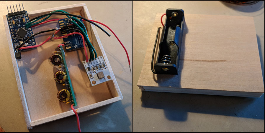
Under Construction
To connect the components of the Flight Computer, I used point to point wiring without any protoboard etc to hold it all together. The electronics will be inside the case and a few dabs of glue will hold it securing in place. This eliminated any additional weight of protoboard.
How much does it weigh? Does this battery make me look fat?
My goal for the Flying Squirrels is to keep weight down to a minimum as that helps reduce the cost of the balloon and the volume of Helium needed. After assembling the Flight Computer and measuring out the antenna wire, the system (minus balloon) weighs 60 grams. In other words the balloon will need to lift 60 grams and have some extra lift to rise. The weight of components breaks down:
30 Meter Antenna wire 18g
Arduino Nano pro 4g
BMP085 2g
Case w Battery holder 10g
LiFePo Battery (400Mah) 15g
Low Pass Filter 6g
SI5351 2g
Misc. wires 1g
Total Weight 60g
I was a bit surprised with the weight of the antenna wire once I clipped my wire to length for the 30 meter band dipole. I used #24 Magnet wire for the antenna. I suppose I could use something thinner, but then I run the risk of the wire being too weak and snapping. If I go to a shorter wave length (higher frequency) it will weigh less. I may still change my mind on the frequency used, so stay tuned. 30 Meters will be the worst-case weight scenario so I will stick with it for initial calculations.
The battery is the next heaviest item. I could find a few battery packs that were lighter but at a significant increase in cost and lower Milliamp/Hour ratings and only slightly reduced weight. Batteries are just heavy items in the scheme of things, so this is the best trade-off of cost vs. performance I have for my goals.
The case is constructed from light weight balsa wood. I tried other light materials like foam and a flexible foam sheet. The balsa is easiest to work with and performs well structurally. The battery holder that I glued onto the case is a typical AA battery holder. It could be replaced, perhaps, with a direct connection of the battery leads to the battery, but I wanted the ability to easily remove and insert the battery at the start of the mission.
The Low Pass Filter (LPF)is heavy due to the three ferrite cores made of Iron. For future flights I may consider a different radio board that produces a sine wave, thus eliminating the need for the LPF
All total the flight computer and antenna weigh in at 60 grams. This is higher than my original weight estimate, however this amount (Just over 2 ounces) can easily be lifted by a slightly larger balloon without significant cost increases.
My Next article will define the FS#1 mission and goals. This will prepare the reader for a following article describing the Flight Controller software.
de KJ6FO