
Whew that’s a mouthful! Let’s just call it a cat sensor instead. However, this board can be used in many scenarios where you need to monitor changes in orientation over long time periods in a remote location. This project will be the battery powered ESP8266 reference design for future Squirrel Engineering projects like weather stations and more.
This project started with a simple request from Squirrel Engineering’s resident cat/animal lover. Can we detect when Spookie (a feral cat) is safely tucked away in his heated shelter during the cold weather. What can I say? It’s good to be a cat around here, free room & board + medical! Sign me up!!

This problem, took more engineering than I initially thought, and I found lots of useful information on the web, but not all in one place. Some of the sources I came across repeat the same information over and over that I think is not correct. (A.K.A Dogma and this article is about cats so no dogma!)
The goal of this article is to share how to build, from start to finish, a battery powered inclinometer that is small, Wi-Fi enabled and will run for extended periods of time without a battery change on a small sized battery.
Sensing a small animal is present or not – How hard can that be?
The first and obvious solution to the problem, was to consider a motion sensor connected to an ESP8266 Wi-Fi Board. All I had to do is, just detect motion and report that back to a networked resource such as a web server. The problem with this approach quickly became apparent. To detect motion, you need to keep watching the subject area over an extended period of time. PIR sensors and Radar based sensors (Ex. RCWL-0516) take time to run and stabilize. Even if you look only periodically, the animal might be sleeping and not moving enough to trigger the motion sensor. Far too much energy has to be consumed to run these sensors on a small battery. More exotic schemes of video monitoring are also way too power hungry to work.
Upon some further reflection, I came up with the idea to measure inclination. (A fancy word for the angle at which something is oriented) Spookie will enter the shelter and lay on the bedding inside. His weight will deform the bedding inside and if the device is resting on the same surface, it should show a change in the surface orientation.
The sensor I chose is an LIS3DH Accelerometer (also called an IMU which is way easier to type than Accelerometer!) The LIS3DH requires very little power and can take measurements from one period to the next with power downs in between measurements. The startup time for the LIS3DH is very quick, so no energy is wasted waiting for the device to stabilize.
Getting Networked!
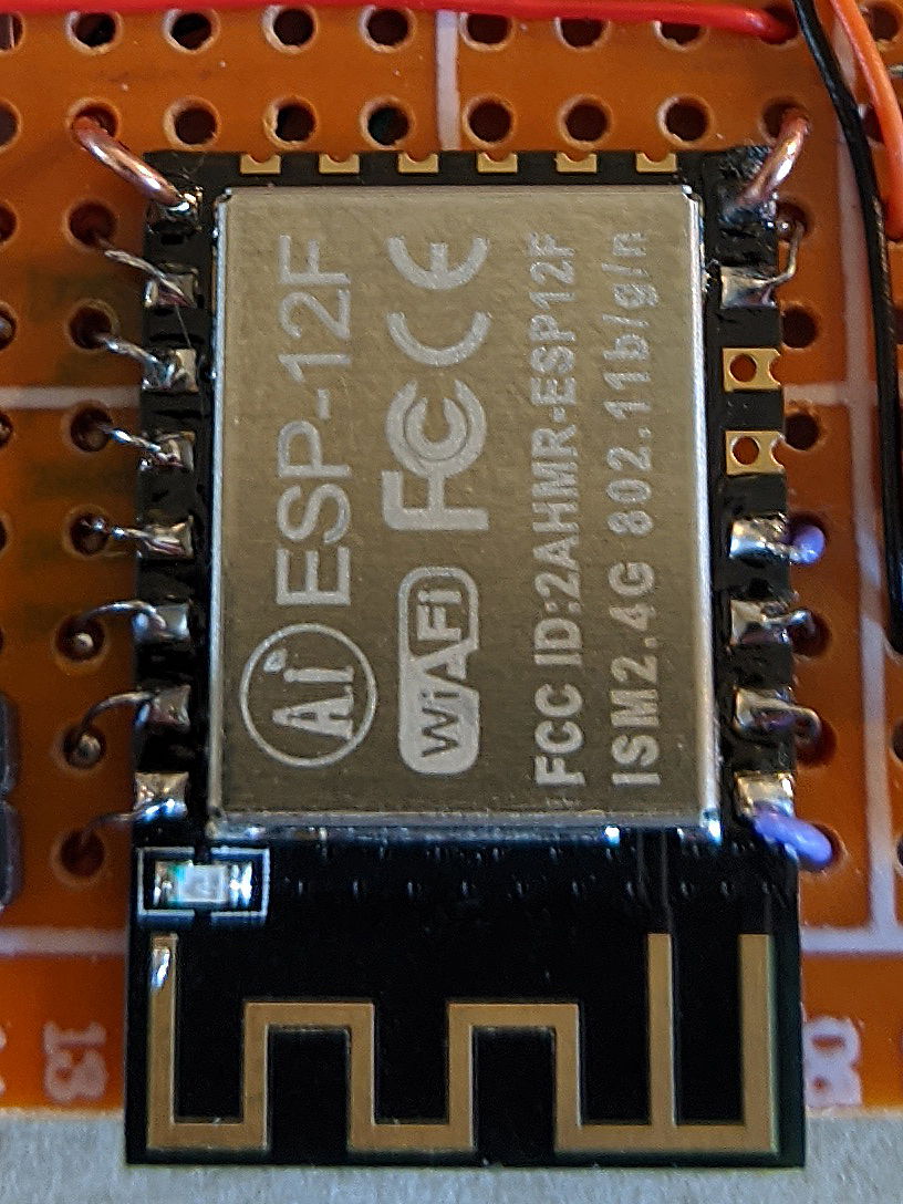
The ESP8266 boards are amazingly effective and cheap devices. It is a Wi-Fi board plus very capable microcontroller all rolled into a postage stamp sized module. Development board versions of the ESP8266 are also available with all the convenient circuitry to make them easy to run and program via a USB port. However, these versions of the boards (NodeMCU & Wemo D1) also consume a lot of power supporting the USB circuitry and other on-board components which are not needed once the project is up and running. To go really low power, the “bare” ESP8266 module will work best. I chose the most recent and currently available module, the ESP-12F. Any ESP module should work for this project except the ESP-01 which does not have enough GPIO pins exposed. The ESP-12F was just the easiest to find for purchase at this point in time.
The ESP8266 board is power hungry consuming 100 mA or more when connecting to the network and running tasks. However, it has a “Deep Sleep” mode that allows the board to go to sleep for a programmable period of time where the power consumption is about 30 uA. This is over 2,000 times less energy used when wake and connecting to the network.
The Design
The strategy of this inclinometer is to take a measurement, report it to a web server and then go beddie-bye (deep sleep) until the next measurement is needed. The longer the device can sleep, the more power will be saved. To sense an animal in a bed, a reading every few minutes will work just fine. Cats don’t use clocks (yet they always know when it is feeding time somehow) and they are not punctual, so a reading every few minutes will be accurate enough for “knowing” if the animal has been in and out of the shelter and when. Does Spookie have a secret life late at night? We may find out.
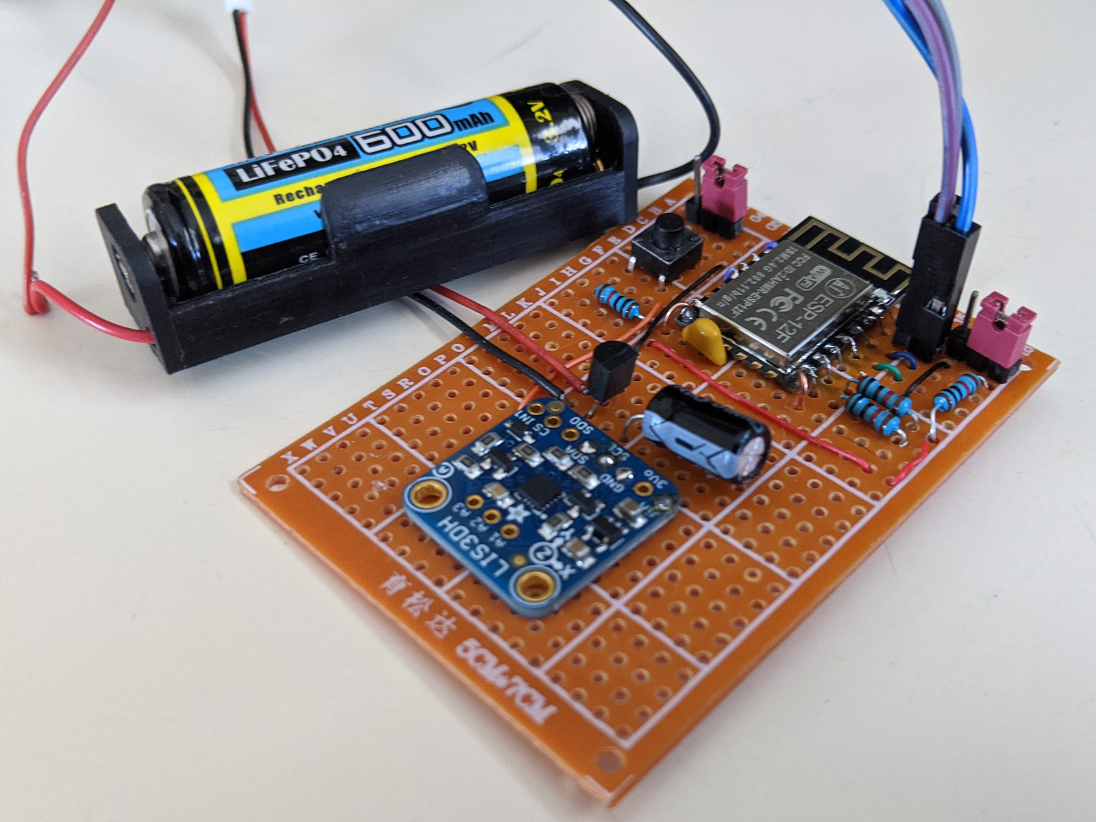
The Board

The schematic circuit for the inclinometer is located at https://github.com/SquirrelEng/ESP8266Inclinometer/blob/master/Doc/Schematic.pdf

The ESP8266 modules use castellated pins that are not the common spacing for most perf/proto boards. Adapters are made that can be used, but I found it easy to adapt the module to a perf board using thin wire. 30 gauge wire wrap wire works very well for this purpose. IMPORTANT: Use a perfboard that does NOT have copper on the side that you are mounting the ESP module to. Due to the different pin spacing, the module can potentially short on any exposed copper pads or traces underneath.
Wirewrap wire is available for a few bucks in a rainbow spool of colors. An example is here. This may be a life-time supply of wire for most of us. The wire is easy to strip just by pinching the insulation between your thumb and finger using your fingernails to pinch and pull. No tools required to strip the ends.
Cut the wires into several inch lengths, strip the end of the wire and insert it into the pin hole on the ESP module and solder it in. Then the wire can be threaded through holes in the proto board and routed to the destination. Wirewrap wire is very flexible but be careful not to be too rough with it as it can break under some stress. This wire is also very useful for routing connections across the board.
For the VCC & Ground pins I used a larger gauge hook up wire just to be safe that the wire can handle the power requirements of the chip. This type of wire is harder to bend so it helps to pre-form it before soldering it. If you don’t have this handy the wirewrap wire will probably work for this too.
If you are really observant, you may notice in the picture, that there is an extra jumper that I thought would be needed. On the NodeMCU and WeMo D1 Dev boards you need to disconnect GPIO 16 and the reset pin reset during programming, but using this board design, this is not necessary. Just ignore this jumper and wire per the schematic diagram.
A raw ESP8266 module operates in one of two modes: 1. Run mode, 2 Programming mode. Actually, there are three modes but this design only supports the two.
To run the board’s program, set the Program/Run jumper (Or switch) to the Run position and power up or press the reset button on the device. It will start running whatever code has been loaded onto the module.
To Program the Board:
The code for this device was created with the Arduino IDE. You will need to add the ESP8266 library to the IDE environment. Instructions on how to program the ESP8266 boards are located Here.
You will need a USB to serial converter, often called a FTDI board. I use a board from SparkFun https://www.sparkfun.com/products/9873 but other models available on Amazon or EBay should also work. Make sure the board you use is 3.3v compatible for the ESP8266 modules.
Wire the Serial IO to the board as follows:
TX – RX
RX-TX
Ground to Ground
Set the Run/Program jumper to the program position and press reset to get the board ready for uploading code. In the Arduino IDE, select the board type as “Generic ESP8266 Module” and select the COM port for your USB to Serial IO bard. If you are running the serial monitor during the bootup, you will see garbage characters on the screen, this is good. Then click on the Arduino IDE upload button to load the program. Once completed, nothing will happen. To now to run your newly uploaded program set the jumper back to the run position and press reset to boot into run mode.
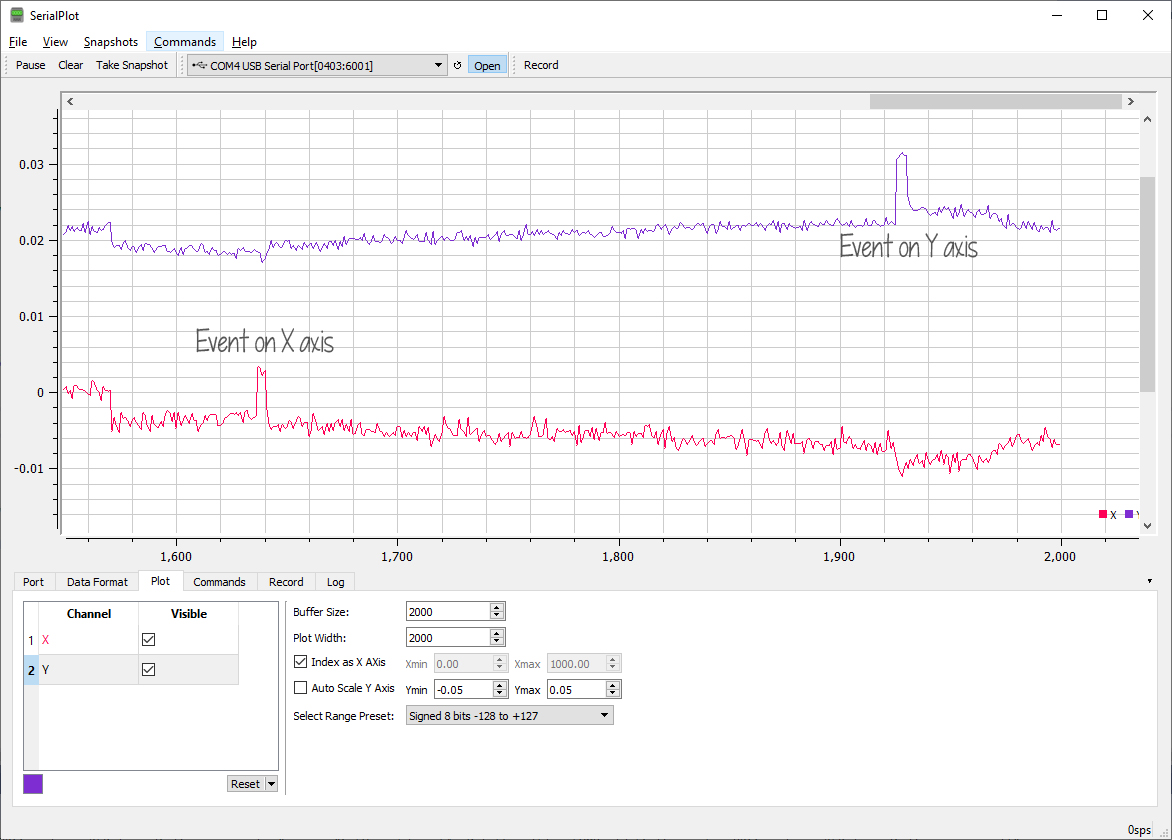
You can leave the serial IO connected if you wish to see what is happening as the board runs. If the DEBUG flag inside the code is set to 1, various output messages will display. If set to zero, only the X & Y IMU values are displayed and this is optional, you can comment out the lines that print this message to the serial IO. I found that the X & Y output was a useful debug/testing aid and for monitoring, the results on a program called SerialPlot which is a very good serial plotter program:
Important Notes About Running the Program:
The board uses 115,200 baud so make sure any serial IO settings are set to this value. If you are watching the board on the serial monitor, you will see a bunch of garbage characters display on screen, followed by the X & Y values a short time later and then nothing. You will see more info with DEBUG enabled (Set to 1). After the X & Y are displayed the ESP8266 goes into deep sleep and will wake up later. When waking up the ESP8266 starts from the beginning and you will see the garbage characters again followed by X &Y. This will be an endless cycle until the battery dies.
If you start the Serial monitor sometime after the boot up, the ESP8266 may be in deep sleep for an extended time and don’t worry that you are seeing nothing on screen. To get an immediate result, just press the reset and it will reboot with the garbage chars.
The garbage chars are boot up diagnostic messages sent by the ESP8266 at a different baud rate. (74,880 baud) Once the program gets running, it changes to 115,200 baud and all looks OK on screen.
Notes About the Code:
The code is located at: https://github.com/SquirrelEng/ESP8266Inclinometer. I use a product called Visual Micro to develop my Arduino code inside the Microsoft Visual Studio IDE. This is not required. You can just open the .ino file like any other Arduino sketch and it will work. If you use Visual Studio with Visual Micro, you can open the .sln file. I developed this sketch using the Community 2019 edition of Visual Studio.
I have tried to document the behavior of the code in source code comments, but I will add a few notes below about the reasons certain things have been done a certain way. For the most part the code is straight forward Arduino code with Wi-Fi.
Get ‘er Done! And Be Quick!
The goal of this program is to get the measurement quickly, report it to the webserver and get back to sleep as quickly as possible. When running, the ESP8266 is consuming power at 2000 times the deep sleep power consumption. To make our battery last a long time the board needs to sleep most of the time. Even an extra few seconds of full power consumption every minute or two will significantly reduce battery life. I found articles that claim to run the ESP8266 on a battery for many months to years. That could be true if you just let the board sleep all the time, but if you run the code for too long your results will fall far short of this goal.
The program calls setup and then does one run through the loop() function before going back to sleep. Each wake up from deep sleep starts the code from the beginning. Other microcontroller boards can wake up where they left off, the ESP8266 does not do this.
The ESP8266 takes some time to connect to the network and if you can set it up with a static IP address, you will save time connecting. By default, the ESP8266 Wi-Fi library code uses DHCP to query your router/gateway for an IP address that it can use on the local area network (LAN). This takes time, so a static IP that has been defined ahead of time will shorten the awake time.
The ESP8266 still takes a few seconds to find and connect to your Wi-Fi access point. Most example code you will find for this starts the connection followed by a while loop waiting for the connection to complete. This makes sense if the very first thing you need to do is send/receive network IOs, but in our case we can use this “dead time” to take samples from our IMU. (LIS3DH) Once the samples have been collected, then we can then check for the connected status and wait if we have to, but most of the time the connection is connected by the time when we need it. The connection process starts in the setup() function with the following code:
// WiFi Setup

WiFi.mode(WIFI_STA); // Station mode.

WiFiMulti.addAP(ssid1, password1);
And the connection is not checked until the Report() function is called after we have our data:
// Wait for the Wi-Fi to connect: scan for Wi-Fi networks, and connect to the strongest of the networks above

while (WiFiMulti.run() != WL_CONNECTED) {

delay(200);

DEBUGOUT('.');

}
Collecting the data:
The LIS3DH IMU can report acceleration, including the force of gravity pulling on the board, in three axis. A perfectly flat and level board will report X = 0, Y = 0 and Z = 1g of gravity. Since we are looking for the deflection in the Spookie’s horizontal bed, the X & Y values are the most important showing changes in relation to “Level” surface.
The actual values reported are not all that important. The goal is to detect a change from prior readings. Any sudden departure from prior readings indicates the board has changed orientation. The change also has to be above some threshold value because the individual readings have small fluctuations. I am not sure what the cause is for these fluctuations, but it is probably just sensor “Noise”.

Individual readings have some significant noise that can be reduced by taking a set of readings and averaging the readings into a single value. The noise appears to be random and this technique will smooth out the data, making the real physical changes easier to detect. Data collection is done in the CollectSamples() function. This function starts up the IMU, collects NSAMPLES of X & Y data, calculates an average X & Y and finally turns off the IMU. It is important that you call delay() or yield() on an ESP8266 during potentially long tasks. This lets it do the Wi-Fi networking in the background. I used delay because we have to wait for the IMU to get its next reading.
void CollectSamples()

{

DEBUGOUT("Collecting data @");

DEBUGOUTLN(millis());


StartIMU(); // Get the IMU running


// Init average values

XAve = 0;

YAve = 0;


// Read samples and sum the values

for (int i = 0; i < NSAMPLES; i++)

{

XAve += myIMU.readFloatAccelX();

YAve += myIMU.readFloatAccelY();


delay(1); // Wait for new sample, Sensor is running at 1600Hz, so sample time is actually less than 1 ms

// ESP8266 needs delay() or yield() to allow it to manage the network connection, so this also helps the ESP8266 run properly.

}


// Calc averages

XAve /= (float) NSAMPLES;

YAve /= (float)NSAMPLES;


IMUPower(false); // Turn off sensor, we are done with it.

}
I set NSAMPLES to 500, but you can experiment with different values. The smaller the value of NSAMPLES is, the faster the routine will execute, but the more noise will be in your data. Conversely, a larger value of NSAMPLES will take longer to collect but will result in more noise removal. I found by experimentation that 500 samples worked well. Feel free to change this value and experiment with your IMU.
Reporting the data
The X & Y data that is collected by the ESP8266 is sent to my webserver. The URL is in the format: http://<domainName>/XYDataPoint.aspx?m=<StationMAC>&x=<xvalue>&y=<yvalue>
You will have to substitute your own web server URL to collect your data. I my case this StationMAC (From the ESP8266 device), X & Y are added to a SQL database, with a time stamp provided by the server. The recorded data looks like this in the database:
<Sample data>
I will develop a web user interface to analyze the data and report on events. This has yet to be developed, so I will write more when I am done with this part of the project.
Which Battery?
I plan on deploying the sensor with a LiP0 18650 battery rated at 3000mah. This should last a good long time. However other battery types will work as well. The board is designed with a LDO (Low Drop out) regulator that will protect the ESP8266 from overvoltage and also allow most of the battery energy to be extracted. Important! A LiPO Battery should have a low voltage cutoff protection circuit built in to keep the battery from being completely discharged and damaged as a result. An alternative battery supply could be 3 AA batteries in series (4.5v). I have also tried a 3.2v LifePo4 battery which works well. Anything that is between 3v and 6v will power the board.
Dogma?
There is a lot of info on the web about how to power up your ESP8266 and it is often repeated that a 1,000 mF Capacitor is needed to clean up and stabilize the power to the ESP8266. This is a very large value capacitor and is also physically big for my small board. Instead I used at 100 uF capacitor and it is working very well. (Will a smaller value work?) Per recommendations on the web, I did add 10 nF capacitor across the ESP8266 Vcc & Ground, as close to the module as I could get. This should clean up any RF noise on the power lines. If you don’t have these parts handy, experiment with other values or try removing these parts completely, and let me know what you discover.
When programming the ESP8266, once you set the programming mode and reset, you do not have to hurry as suggested in many articles that say hit reset just as the code starts compiling. The ESP8266 will happily wait for the program to be compiled and uploaded and you can even upload again without any further actions.
How Long Will It Run?
My board is sleeping two minutes and then waking up for a few seconds (It will vary due to the network connection time, but usually less than 3 seconds) According to my calculations the board is drawing and average of 1.81 mA per minute. According to this handy online calculator: https://www.digikey.com/en/resources/conversion-calculators/conversion-calculator-battery-life my run time will be 1657 hrs and 27 mins. That’s is about 105 days. Only real-world trials will verify this, but the numbers look like my LiPo battery will last throughout the cold season here in Southern California. Stay tuned for updates in a few months.
Next Steps
The Inclinometer board is complete and is ready to be mounted into an enclosure. I will publish an update once the board is enclosed and ready to go outside for real world testing.
Will the board run as long as expected? I will perform initial tests with a 600 mAH LifePo4 3.2v battery (As shown in picts above)
Will the sensor actually detect Spookie in his shelter? UPDATE: After collecting data for a few days, the answer to this question is YES! See this post for details.
Stay tuned.
73s de Don KJ6FO