
FS7 – The Flying Squirrel #1 Flight controller software
 The FS#1 flight controller is designed to measure basic weather information (Barometric Altitude, Air Pressure and Temperature) and relay that information periodically to the ground via radio telemetry using the FSQ protocol. Additionally, the flight controller conserves battery power by turning off the radio and weather sensor between transmissions.
In a nutshell the FS#1 flight controller will do the following:
- Initialize the Arduino pins, pre-calculate some variables and other typical initializations in setup()
- Start a forever loop (i.e. the loop() function)
- On each loop the system will:
- Increment a loop counter, counting the # of loops performed.
- Power up and configure the weather sensor board and radio board.
- Take weather measurements.
- Format a telemetry message string to be sent.
- Send a CW carrier for 5 seconds to help fine tuning adjustments to the receiver tuning before telemetry data is sent.
- Send the telemetry message via FSQ protocol (alternates between 2 & 6 baud on each loop) on the chosen frequency.
- Turn off power to the weather sensor and radio.
- Sleep for one minute and then end the loop.
Sample telemetry:
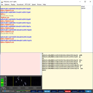
The following is a sample of the first five telemetry messages sent by FS#1. This data was from a test run that was on my workbench. You can see there is some “movement” in the data which is just noise.
The measurements are in metric units of Meters, Celsius and Pascals (Hecto-Pascals)
kj6fo/b:c2allcall#[fs1.txt]1|0|434.06m|20.8c|962.19p|63
kj6fo/b:c2allcall#[fs1.txt]2|3|434.06m|21.2c|962.19p|2c
kj6fo/b:c2allcall#[fs1.txt]3|0|434.58m|21.6c|962.13p|bb
kj6fo/b:c2allcall#[fs1.txt]4|3|434.58m|21.8c|962.13p|55
kj6fo/b:c2allcall#[fs1.txt]5|0|434.75m|22.0c|962.11p|68
Decomposing the first message:
kj6fo/b:c2allcall#[fs1.txt]1|0|434.06m|20.8c|962.19p|63
The first part of every message is information that is required by ham radio rules and also part of the FSQ protocol.
kj6fo/b:c2allcall#[fs1.txt]
kj6fo/b is my radio callsign with /b added for balloon.
:c2 is a CRC check digit calculated from my callsign. This is used at the receiving end to validate my call sign was received correctly.
allcall is the “To” field, in this case the message is directed to everyone listening.
[fs1.txt] is a FSQ command asking the receiver to record the message body into a file called fs1.txt
The last part of the message is the FS#1 telemetry information:
1|0|434.06m|20.8c|962.19p|63
The “|” character is used to separate the data fields.
1 – indicated this is the first message to be sent.
0 – is the baud rate enumeration. 0 is 6 baud and 3 is 2 baud. FS#1 telemetry alternates between these two speeds on each transmission.
434.06m – altitude in meters
20.8c – temperature in Celsius
962.19p – barometric pressure in hecto-pascals.
63 is a message CRC check digit used to validate the contents of the telemetry message.
What is a Cyclic Redundancy Check?
A cyclic redundancy check (CRC) is an error-detecting code commonly used in digital networks and storage devices to detect accidental changes to raw data. For more information visit Wikipedia.
The code:
I documented the code with plenty of comments. I will only describe a few portions of the code here.
The FSQ protocol code was adapted from work published by a number of other hams. The details are documented in the comments at the top of the Arduino sketch. My major change to the FSQ code was to change the timing from interrupt based timing logic to using delays(). Interrupt based timing is more accurate than the delays, but it is also not portable between different processor speeds. With more and more new Arduino compatible devices coming into availability, I decided to make the change to delays() functions. The delay() function is accurate enough for the slow baud rates of FSQ. The BaudDelay() function delays the appropriate amount of time for each character sent and the start of the next character.
Libraries:
The Si5351A board I am using is from Adafruit, however I am using the EtherKit library because it was easier to work with when selecting frequencies. The remaining libraries are the normal ones for the hardware used.
#include <si5351.h>
#include "Wire.h"
#include <Adafruit_Sensor.h>
#include <Adafruit_BMP085_U.h>
Defines & Global values:
At the top of the file there are a number of Defines and globals that control the behavior of the flight controller.
The first define, DIALFREQUENCY, sets the desired dial frequency of the receiver in Hertz. Make sure this value is set to a frequency that you are legally allowed to use. FS#1 will transmit at 28.140Mhz (28140000 Hz).
The Si5351A boards have some variances in the frequency they output from the desired frequency. The following defines are used to set the board to the actual desired dial frequency.
CALIBRATIONADJUST is an adjustment factor you can use to calibrate the SI5351A, if you can accurately compare the Si5351a to a stable frequency standard. Because I don’t have a suitable frequency counter, I left this value at zero and used the define FREQADJUST instead.
The value of FREQADJUST was determined by through a trial and error process. I tuned in the telemetry on my receiver to the dial frequency and noticed the amount of error from the SI5351A. Then I adjusted FREQADJUST by this error amount and repeated the process until I had the signal fine-tuned. It is important to note, the Si5351A board will drift in frequency with temperature changes so, in the field, your frequency may be different than where you calibrated it.
Frequencies on the Si5351A board are specified in 100ths of hertz, but to keep the code easier to read the defines in Hertz and will be multiplied by 100 later in the code when the Si5351A is set to the frequency..
The base transmit frequency is calculated as (28140000UL + 1350UL + FREQADJUST) which puts the transmitter at a dial frequency of 28.140 Mhz. The FSQ tones start at 1350hz above the carrier frequency so this value is added to the dial frequency. The frequency adjustment is then added to this number to calculate the desired dial frequency.
The define TONE_SPACING defines the tone spacing of the FSQ characters. FSQ uses tones 8.7890625Hz apart. The SI5351A has a tuning resolution of 100ths of Hertz so we use the value 879 (8.79 Hz) for this tone spacing. It is close enough in value to work.
// The receievers dial frequency (i.e. the frequency you tune to) in Hertz
#define DIALFREQUENCY 28140000UL

// Adjusted to individual boards as needed.
#define CALIBRATIONADJUST 0

// Each Si5351A is slightly different. The FREQADJUST is an offset to the desired dial frequency to compensate for board variances.
// Defined in Hertz
#define FREQADJUST (-450LL) // Trial and Error adjustment for 10m band

// Global variables
unsigned long Frequency = (DIALFREQUENCY + 1350UL + FREQADJUST); // Base freq is 1350 Hz higher than dial frequency in USB
FSQ tones are separated by 8.7890625hz. TONE_SPACING specifies the closest value in 100th Hertz.
// FSQ Defines and data
#define TONE_SPACING 879ULL // ~8.7890625 Hz
The following section defines the Baud Rates, between 2 and 6 baud, supported by FSQ.
//Baud Rates
#define BAUD_2 1000 // Delay in ms value for 2 baud
#define BAUD_3 667 // Delay in ms value for 3 baud
#define BAUD_4_5 445 // Delay in ms value for 4.5 baud
#define BAUD_6 333 // Delay in ms value for 6 baud

enum BaudEnum // Index into BaudDelayTable
{
Baud6 = 0,
Baud45 = 1,
Baud3 = 2,
Baud2 = 3
};

int BaudDelayTable[4] = { BAUD_6 ,BAUD_4_5 ,BAUD_3,BAUD_2 };
BaudEnum CurrentBaud = Baud6; // Deafult baud rate
The SLEEPYTIME define specifies the delay between the end of one transmission the start of the next. FS#1 will delay one minute between transmission.
// Interval from the last Xmit to the start of the next Xmit.
#define SLEEPYTIME (1000L*60L*1L) // 1 min
char MyCallSign[10] = “YOUR_CALL_SIGN_GOES_HERE”; sets the callsign of the balloon. Be sure to change this to your own callsign.
The rest of the defines and globals are part of the FSQ protocol and deine the character table used in sending FSQ.
Key functions:
The functions are well documented in the code, so I will just give a brief description of the important functions here.
setup() – The standard Arduino function used to initialize the program variables and hardware pins etc. The CRC tables and the callsign CRC is computed here. The power management Pin is initialized and powered “Off”.
loop() – the main Arduino loop function. This function performs the steps of the loop described above.
XmitTelemetry() – Sends the telemetry message via the radio.
XmitCharacter() – Sends a FSQ character
XmitTone() – Sets the radio to the frequency needed for the character being sent.
BaudDelay() – Waits the appropriate time for the transmission to continue on to the next character. (I.e. the time length of the character)
ComposeTelemetryMsg() – Formats the sensor information into the Telemetry string.
StartRadio() – This function initializes the Si5351A board after it is powered up and gets it ready to transmit.
StartSensor() – This function initializes the BMP085 weather module after power up
PowerOn() – Powers up the radio and weather boards by turning the POWERENABLEPIN pin to high which turns on the 2n7000 switch in the circuit.
PowerOff() – Set the POWERENABLEPIN to low which cuts power to the radio and weather board.
The Full Code:
Kj6FO_FS1.ino
//
//
// Flying Squirrel Flight #1 code By Don Gibson KJ6FO
// FSQ Protolcol adpated from work done By Jason Milldrum NT7S
// All comments below the legal stuff imeediately below are notes
// by Don Gibson. See http://SquirrelEngineering.com for more details.
//
//
// Simple FSQ telemetry beacon for Arduino, with the Etherkit Si5351A
// Breakout Board, by Jason Milldrum NT7S.
//
// Original code based on Feld Hell beacon for Arduino by Mark
// Vandewettering K6HX, adapted for the Si5351A by Robert
// Liesenfeld AK6L <ak6l@ak6l.org>. Timer setup
// code by Thomas Knutsen LA3PNA.
//
// Telemetry is sent in the following format:
// <temp>|<rel humidity>|<date><time>|<CRC-8 checksum>
//
// The CRC-8 checksum is done on the entirety of the telemetry
// string, including the pipe characters.
//

//
// Permission is hereby granted, free of charge, to any person obtaining
// a copy of this software and associated documentation files (the
// "Software"), to deal in the Software without restriction, including
// without limitation the rights to use, copy, modify, merge, publish,
// distribute, sublicense, and/or sell copies of the Software, and to
// permit persons to whom the Software is furnished to do so, subject
// to the following conditions:
//
// The above copyright notice and this permission notice shall be
// included in all copies or substantial portions of the Software.
//
// THE SOFTWARE IS PROVIDED "AS IS", WITHOUT WARRANTY OF ANY KIND,
// EXPRESS OR IMPLIED, INCLUDING BUT NOT LIMITED TO THE WARRANTIES OF
// MERCHANTABILITY, FITNESS FOR A PARTICULAR PURPOSE AND NONINFRINGEMENT.
// IN NO EVENT SHALL THE AUTHORS OR COPYRIGHT HOLDERS BE LIABLE FOR
// ANY CLAIM, DAMAGES OR OTHER LIABILITY, WHETHER IN AN ACTION OF
// CONTRACT, TORT OR OTHERWISE, ARISING FROM, OUT OF OR IN CONNECTION
// WITH THE SOFTWARE OR THE USE OR OTHER DEALINGS IN THE SOFTWARE.
//

#include <si5351.h>
#include "Wire.h"
#include <Adafruit_Sensor.h>
#include <Adafruit_BMP085_U.h>

// The receievers dial frequency (i.e. the frequency you tune to) in Hertz
#define DIALFREQUENCY 28140000UL

// Adjusted to individual boards as needed.
#define CALIBRATIONADJUST 0

// Each Si5351A is slightly different. The FREQADJUST is an offset to the desired dial frequency to compensate for board variances.
// Defined in Hertz
#define FREQADJUST (-450LL) // Trial and Error adjustment for 10m band

// Global variables
unsigned long Frequency = (DIALFREQUENCY + 1350UL + FREQADJUST); // Base freq is 1350 Hz higher than dial frequency in USB

// FSQ Defines and data
#define TONE_SPACING 879ULL // ~8.7890625 Hz

//Baud Rates
#define BAUD_2 1000 // Delay in ms value for 2 baud
#define BAUD_3 667 // Delay in ms value for 3 baud
#define BAUD_4_5 445 // Delay in ms value for 4.5 baud
#define BAUD_6 333 // Delay in ms value for 6 baud

enum BaudEnum // Index into BaudDelayTable
{
Baud6 = 0,
Baud45 = 1,
Baud3 = 2,
Baud2 = 3
};

int BaudDelayTable[4] = { BAUD_6 ,BAUD_4_5 ,BAUD_3,BAUD_2 };
BaudEnum CurrentBaud = Baud6; // Deafult baud rate

// Onboard LED used to indicate transmitting status. Not essential to the function of the flight and could be removed
// if more power savings is desired.
#define LED_PIN 13

//POWER MGMT
// Pin used to control the on/off state of the transmitter board and sensor, to conserve power when not in use.
#define POWERENABLEPIN 9

// Interval from the last Xmit to the start of the next Xmit.
#define SLEEPYTIME (1000L*60L*1L) // 1 min

// Global vars for telemetery data
// Using metric data values to keep the telemetry data shorter, requiring less transmit time and power consumtion.
long XmitCount = 0L; // Count of xmit cycles.
float AltM = 0.0; // Barrometric altitude in meters. Based on standard sea level value.
float hPA = 0.0; // Barrometric pressure in Pascals*100
float TempC = 0.0; // Temp C

// Class instantiation
Si5351 si5351; //Our radio board
Adafruit_BMP085_Unified bmp = Adafruit_BMP085_Unified(10085); // Presure and temp sensor

//
// FSQ Protocol vars and data structures.
//

// Init FSQ
uint8_t cur_tone = 0; // Current FSQ tone
static uint8_t crc8_table[256];
char ToCallSign[10] = "allcall";
char MyCallSign[10] = "YOUR_CALL_SIGN_GOES_HERE"; // Change to your own callsign
char tx_buffer[200];
uint8_t MyCallsign_CRC;

// Define the structure of a varicode table
typedef struct fsq_varicode
{
uint8_t ch;
uint8_t var[2];
} Varicode;

// The FSQ varicode table, based on the FSQ Varicode V3.0
// document provided by Murray Greenman, ZL1BPU

const Varicode code_table[] PROGMEM =
{
{ ' ',{ 00, 00 } }, // space
{ '!',{ 11, 30 } },
{ '"',{ 12, 30 } },
{ '#',{ 13, 30 } },
{ '$',{ 14, 30 } },
{ '%',{ 15, 30 } },
{ '&',{ 16, 30 } },
{ '\'',{ 17, 30 } },
{ '(',{ 18, 30 } },
{ ')',{ 19, 30 } },
{ '*',{ 20, 30 } },
{ '+',{ 21, 30 } },
{ ',',{ 27, 29 } },
{ '-',{ 22, 30 } },
{ '.',{ 27, 00 } },
{ '/',{ 23, 30 } },
{ '0',{ 10, 30 } },
{ '1',{ 01, 30 } },
{ '2',{ 02, 30 } },
{ '3',{ 03, 30 } },
{ '4',{ 04, 30 } },
{ '5',{ 05, 30 } },
{ '6',{ 06, 30 } },
{ '7',{ 07, 30 } },
{ '8',{ 8, 30 } },
{ '9',{ 9, 30 } },
{ ':',{ 24, 30 } },
{ ';',{ 25, 30 } },
{ '<',{ 26, 30 } }, { '=',{ 00, 31 } }, { '>',{ 27, 30 } },
{ '?',{ 28, 29 } },
{ '@',{ 00, 29 } },
{ 'A',{ 01, 29 } },
{ 'B',{ 02, 29 } },
{ 'C',{ 03, 29 } },
{ 'D',{ 04, 29 } },
{ 'E',{ 05, 29 } },
{ 'F',{ 06, 29 } },
{ 'G',{ 07, 29 } },
{ 'H',{ 8, 29 } },
{ 'I',{ 9, 29 } },
{ 'J',{ 10, 29 } },
{ 'K',{ 11, 29 } },
{ 'L',{ 12, 29 } },
{ 'M',{ 13, 29 } },
{ 'N',{ 14, 29 } },
{ 'O',{ 15, 29 } },
{ 'P',{ 16, 29 } },
{ 'Q',{ 17, 29 } },
{ 'R',{ 18, 29 } },
{ 'S',{ 19, 29 } },
{ 'T',{ 20, 29 } },
{ 'U',{ 21, 29 } },
{ 'V',{ 22, 29 } },
{ 'W',{ 23, 29 } },
{ 'X',{ 24, 29 } },
{ 'Y',{ 25, 29 } },
{ 'Z',{ 26, 29 } },
{ '[',{ 01, 31 } },
{ '\\',{ 02, 31 } },
{ ']',{ 03, 31 } },
{ '^',{ 04, 31 } },
{ '_',{ 05, 31 } },
{ '`',{ 9, 31 } },
{ 'a',{ 01, 00 } },
{ 'b',{ 02, 00 } },
{ 'c',{ 03, 00 } },
{ 'd',{ 04, 00 } },
{ 'e',{ 05, 00 } },
{ 'f',{ 06, 00 } },
{ 'g',{ 07, 00 } },
{ 'h',{ 8, 00 } },
{ 'i',{ 9, 00 } },
{ 'j',{ 10, 00 } },
{ 'k',{ 11, 00 } },
{ 'l',{ 12, 00 } },
{ 'm',{ 13, 00 } },
{ 'n',{ 14, 00 } },
{ 'o',{ 15, 00 } },
{ 'p',{ 16, 00 } },
{ 'q',{ 17, 00 } },
{ 'r',{ 18, 00 } },
{ 's',{ 19, 00 } },
{ 't',{ 20, 00 } },
{ 'u',{ 21, 00 } },
{ 'v',{ 22, 00 } },
{ 'w',{ 23, 00 } },
{ 'x',{ 24, 00 } },
{ 'y',{ 25, 00 } },
{ 'z',{ 26, 00 } },
{ '{',{ 06, 31 } },
{ '|',{ 07, 31 } },
{ '}',{ 8, 31 } },
{ '~',{ 00, 30 } },
{ 127,{ 28, 31 } }, // DEL
{ 13,{ 28, 00 } }, // CR
{ 10,{ 28, 00 } }, // LF
{ 0,{ 28, 30 } }, // IDLE
{ 241,{ 10, 31 } }, // plus/minus
{ 246,{ 11, 31 } }, // division sign
{ 248,{ 12, 31 } }, // degrees sign
{ 158,{ 13, 31 } }, // multiply sign
{ 156,{ 14, 31 } }, // pound sterling sign
{ 8,{ 27, 31 } } // BS
};

// Define an upper bound on the number of glyphs. Defining it this
// way allows adding characters without having to update a hard-coded
// upper bound.
#define NGLYPHS (sizeof(code_table)/sizeof(code_table[0]))

//
// Get the hardware and program set up.
//
void setup()
{
// Init serial for debug and GPS
Serial.begin(9600);

// Use the Arduino's on-board LED as a keying indicator.
pinMode(LED_PIN, OUTPUT);
digitalWrite(LED_PIN, LOW);

// Set up power control pin. This pin will turn on/off radio & sensor etc.
pinMode(POWERENABLEPIN, OUTPUT);
PowerOff(); // Off

init_crc8(); // Initialize the CRC table

// Generate the CRC for the MyCallSign
MyCallsign_CRC = crc8(MyCallSign);

Serial.println("Setup complete.");

}

//
// Program loop
//
void loop()
{
Serial.println("Loop");

// Turn on power to radio and sensor, init sensor.
PowerOn();
StartRadio();
StartSensor();

// Get sensor data
/* Get a new sensor event */
sensors_event_t event;
bmp.getEvent(&event);

// (barometric pressure is measure in hPa)
if (event.pressure)
{
hPA = event.pressure;

/* Display atmospheric pressue in hPa */
Serial.print("Pressure: ");
Serial.print(event.pressure);
Serial.println(" hPa");

/* Calculating altitude with reasonable accuracy requires pressure *
* sea level pressure for your position at the moment the data is *
* converted, as well as the ambient temperature in degress *
* celcius. If you don't have these values, a 'generic' value of *
* 1013.25 hPa can be used (defined as SENSORS_PRESSURE_SEALEVELHPA *
* in sensors.h), but this isn't ideal and will give variable *
* results from one day to the next. *
* *
* You can usually find the current SLP value by looking at weather *
* websites or from environmental information centers near any major *
* airport. *
* *
* For example, for Paris, France you can check the current mean *
* pressure and sea level at: http://bit.ly/16Au8ol */

/* First we get the current temperature from the BMP085 */

bmp.getTemperature(&TempC);

/* Then convert the atmospheric pressure, and SLP to altitude */
/* Update this next line with the current SLP for better results */
float seaLevelPressure = SENSORS_PRESSURE_SEALEVELHPA;

AltM = bmp.pressureToAltitude(seaLevelPressure, hPA);

}
else // default to zero values.
{
Serial.println("Sensor error");

// Zero values so we dont get old readings.
AltM = 0.0;
hPA = 0.0;
TempC = 0.0;
}

//
// Send Telemetery
//

XmitCount++; //Increment loop count

// To evaluate the differences between baud rates, FS#1 will change baud rates on each transmission.
// This is not essential code and you can change this without issues.
//Alternate Baud Rates between 6 and 2 baud on alternating transmissions
if (XmitCount % 2)
{
CurrentBaud = Baud6;
}
else
{
CurrentBaud = Baud2;
}

// Format Telemetry
ComposeTelemetryMsg();
Serial.print("Telem=");
Serial.println(tx_buffer);

// Send telemetry
Serial.println("Xmit start");
XmitTelemetry(tx_buffer);
Serial.println("Xmit done");

// Turn Off POWER to radio and sensor
PowerOff();

delay(SLEEPYTIME); // Rest until next time.
}

//
// FSQ functions
//

// Send the telemetery string. Loop through the string, transmitting one character at a time.
void XmitTelemetry(char *str)
{
Serial.println("Xmit Telem() start");
// Reset the tone to 0 and turn on the output
cur_tone = 0;

si5351.output_enable(SI5351_CLK0, 1); // Enable Radio output on Clk0 pin
digitalWrite(LED_PIN, HIGH); //Turn on LED to show Xmit is on.

delay(500); // Warm up the xmitter board output. May depend on frequency. Higher freqs are less stable, maybe longer.

// Transmit a tone to aid in tuning the reciever. Freq will drift as tempreture changes. This gives you 5 seconds to fine tune the receiver.
XmitTone(0); //Transmit space tone - used to adjust rcvr.
delay(5000); // Transmit for 5 sec. Adjust or remove this line as desired.

//
// Start of FSQ protocol
//

Serial.println("Xmit Telem() BOT");
// Begin of Transmission sequence
// The normal BOT is two spaces followed by LF

for (int i = 0;i < 2;i++)
{
// Transmit BOT Sequence
XmitCharacter(' '); // Send a space for the dummy character
BaudDelay();
}
// Now send LF (BOT)
XmitCharacter(10);
BaudDelay();

// Transmit the telemetry message
Serial.println("Xmit Telem() message");

while (*str != '\0')
{
XmitCharacter(*str++);
}

// Turn off the output
si5351.output_enable(SI5351_CLK0, 0); // Disable output
digitalWrite(LED_PIN, LOW); // Turn off Transmit LED
Serial.println("Xmit Telem() end");
}

// Given a character, it finds the
// appropriate glyph and sets output from the Si5351A to key the
// FSQ signal.
void XmitCharacter(int ch)
{
uint8_t i, fch, vcode1, vcode2;

for (i = 0; i < NGLYPHS; i++)
{
// Check each element of the varicode table to see if we've found the
// character we're trying to send.
fch = pgm_read_byte(&code_table[i].ch);

if (fch == ch)
{
// Found the character, now fetch the varicode chars
vcode1 = pgm_read_byte(&(code_table[i].var[0]));
vcode2 = pgm_read_byte(&(code_table[i].var[1]));

// Transmit the appropriate tone per a varicode char
if (vcode2 == 0)
{
// If the 2nd varicode char is a 0 in the table,
// we are transmitting a lowercase character, and thus
// only transmit one tone for this character.

// Generate tone
XmitTone(vcode1);
BaudDelay();
}
else
{
// If the 2nd varicode char is anything other than 0 in
// the table, then we need to transmit both

// Generate 1st tone
XmitTone(vcode1);
BaudDelay();
// Generate 2nd tone
XmitTone(vcode2);
BaudDelay();
}
break; // We've found and transmitted the char,
// so exit the for loop
}
}
}

// Transmit the next character tone.
void XmitTone(uint8_t tone)
{
cur_tone = ((cur_tone + tone + 1) % 33);
//Serial.println(cur_tone);
uint64_t ToneFreq = (Frequency * SI5351_FREQ_MULT) + (cur_tone * TONE_SPACING);
si5351.set_freq(ToneFreq, SI5351_CLK0);
}

// Delay based on the current baud rate we are using. This is the duration a character tone will be sent.
void BaudDelay()
{
delay(BaudDelayTable[CurrentBaud]);
}

//
// CRC functions
//

// Init CRC table
static void init_crc8(void)
{
int i, j;
uint8_t crc;

for (i = 0; i < 256; i++)
{
crc = i;
for (j = 0; j < 8; j++)
{
crc = (crc << 1) ^ ((crc & 0x80) ? 0x07 : 0);
}
crc8_table[i] = crc & 0xFF;
}
}

// Calc CRC
uint8_t crc8(char * text)
{
uint8_t crc = '\0';
uint8_t ch;
int i;
for (i = 0; i < strlen(text); i++)
{
ch = text[i];
crc = crc8_table[(crc) ^ ch];
crc &= 0xFF;
}

return crc;
}

//
// Telemtry functions
//

// Compose telemetry message
//
// Message format:
//
// callsign:crc allcall #[logfile.txt] -- Note spaces are added for readability, they are not part of the message.
// Count|Baud Enum|Altitude (estimate)|Temp (Deg C)|Pressure (Pascals)|CRC
//
// Example: kj6fo/b:c2allcall#[fs1.txt]2|3|417.23m|21.3c|964.13p|e1
// From kj6fo/b:c2 My call with crc check (c2)
// To allcall
// Log to file fs1.txt
// Trasmission #2
// 2 Baud -- 3 is enum value for 2 baud
// 417.23m Altitude (Barrometric)
// 21.3c Temprature.
// 964.13p Barrometric pressure
// e1 Message CRC
//
// See BaudEnum for the list of baud rates
//
void ComposeTelemetryMsg(void)
{
char telemetry[100];
uint8_t telem_check;

telemetry[0] = 0;

//String TelemStr = String(XmitCount)+"|"+ String((int)CurrentBaud) + "|" + String(hPA, 2) + "p|" + String(AltM, 2) + "m|" + String(TempC, 1) + "c|";
String TelemStr = String(XmitCount) + "|" + String((int)CurrentBaud) + "|" + String(AltM, 2) + "m|" + String(TempC, 1) + "c|" + String(hPA, 2) + "p|";
strcpy(telemetry, TelemStr.c_str());

telem_check = crc8(telemetry);

sprintf(tx_buffer, "%s:%02x%s#[fs1.txt]%s%02x%s",
MyCallSign, MyCallsign_CRC, ToCallSign, telemetry, telem_check, " \b ");

}

//
// Get the radio board set up and ready to transmit
//
void StartRadio()
{
delay(200); // the radio needs a slight "Warm up" time, after power up
Serial.println("Init si5351 start");
si5351.init(SI5351_CRYSTAL_LOAD_8PF, 0, 0);

Serial.println("Init si5351 done");

// Set CLK0 output

si5351.set_correction(CALIBRATIONADJUST); // Measured value from calibration program
si5351.set_freq(Frequency * SI5351_FREQ_MULT, SI5351_CLK0);
si5351.drive_strength(SI5351_CLK0, SI5351_DRIVE_8MA); // Set for max power if desired
si5351.output_enable(SI5351_CLK0, 0); // Disable the clock initially
delay(200); // Warm up Needed?
Serial.println("si5351 Started");
}

//
// Start up weather sensor board
//
void StartSensor()
{
/* Initialize the BMP085 sensor */
if (!bmp.begin())
{
/* There was a problem detecting the BMP085 ... check your connections */
Serial.print("Ooops, no BMP085 detected");
}
}

//
// Power Management functions
//

void PowerOn()
{
digitalWrite(POWERENABLEPIN, HIGH);
}

void PowerOff()
{
digitalWrite(POWERENABLEPIN, LOW);
}